Tuesday, March 28, 2023

Upgrading Pinky's Ankle Servos

 I've decided to upgrade from sg90s to mg996Rs.

Since there is such a significant size difference, I'll have to do some redesigns. I'll start with the gearing. Since I still want to reduce the servo's natural 180-degree movement into 90-degree ankle movement, I'll implement a 2:1 gear ratio. This will limit the range of motion and increase the torque.

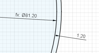
The servo shaft adapter requires an 8.75mm center hole, so I'll bump that up to 8.85 for clearance. 3D-printed plastic also shrinks a little. Other parameters for the 996 spur gear; Metric, 20 degree pressure angle, module = 1, #Teeth 24, backlash 0, root fillet radius .5mm, gear thickness 5mm. This is quite a large gear and the foot's gear will have to be twice as large! A 48mm foot gear is going to be too large.

OK, next attempt. Remix a servo horn from Thingiverse to mesh with the original drive gear.
The horn adapter fits!/
4/13/23 UPDATE:
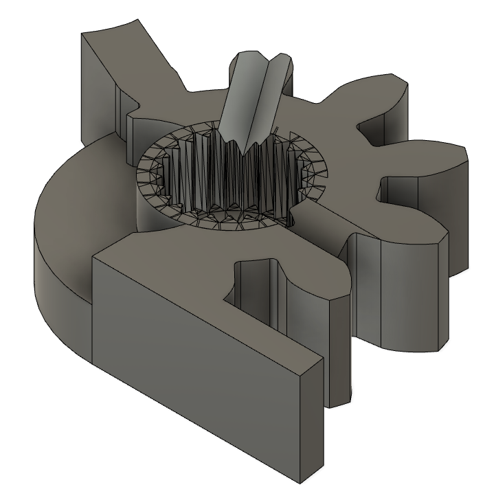
Decided to move the MG996Rs to the knee joints and 995s to the ankles. For the ankles, I set the servo driver to 800 for it to be straight. The knees were set to 2200 straight. Straight means 0-degree bend.
Hips do not need recalibration. Calibration app:https://ai2.appinventor.mit.edu/b/3is9x
0. -
1. -
2. -
3. - Knee Recalibrated
4. ReCalibrated
5. 
6. 
7. Knee Recalibrated
Waiting on prints.
4/14
the foot weighs 1.8g, 2.8 with bearing.
The thigh weighs 18g with bearing.8 without.


Wednesday, March 8, 2023

Drone Design

Drone Design for Bellingham Coding and Robotics Club

Goals: 

  • Learn basic Fusion 360 (CAD) skills.
  • Learn about drone components.
  • Learn electronics.
  • Learn flight tuning.
  • Learn piloting skills.
Components:

Fusion Process:

  1. Download and install Fusion 360.
  2. Sign up for a free account.
  3. Open Fusion.
  4. Create a new design. ( CTL+N )
  5. Save your file ( CTL-S ).
    1. Name your design.
  6. Open the parameters window.
  7. Add the following parameters, then click OK:
  8. Create a new sketch:
    1. Click on the top of the navigation cube:

    2. Select the XY plane as your sketch plane by selecting the orange square:
  9. Create a center point rectangle:
    1.     Select the origin as your center point and enter the motor mount parameter as your dimensions for the rectangle. Hit the tab key to switch between the two dimensions.

    2. Click "Finish Sketch".

  10. Create a new component:
    1. Name the new component "MotorMount", then click OK.
    2. Create a new sketch. The image below will be the finished sketch.

      1. Press the P key to project. Select a corner point from the rectangle on your previous sketch. Click OK.
      2. Create a "center point circle" by pressing the C key or clicking its icon.
      3. With its center being the point you just projected, move the mouse slightly and enter the motormount parameter you set earlier. It should be 6.6mm. Click on the circle and hit the "x" key to turn it into a reference line. This is shown above in YELLOW.
      4. Hit the "O" key and click on the circle just created to offset the circle. I offset mine by 3.1, shown in MAGENTA above. This will NOT be a reference line. If it is dashed, click the circle and hit "x".
      5. Create a hole for the motor shaft by creating another center point circle in the center of the motor mount with a diameter of 3mm. Shown in BLUE above.
      6. Press the "L" key to open the line tool. Click on the sketch's origin (center of the drawing with the black and white circles), then click the center of your motor mount. Then, create another line from the center of the motor mount to the 6.6mm reference circle. You'll see a mark that looks like "//" when the lines are parallel. Both of these lines should be reference lines.
      7. Create a center point circle using the motorMountScrew parameter for the diameter. Mine is 1.5mm, shown in GREEN above.
      8. To create two more equally spaced circles, use the circular pattern tool.
      9. Select the circle you just created, and the center point will be the center of the motor mount. Click OK.
      10. Once your sketch resembles the marked-up sketch, you are ready to extrude. Click finish sketch.
    3. Extrude your drawing 3mm. Press the "E" key, click the extrude icon, or select CREATE > EXTRUDE. When you mouse over your motor mount profile, It'll all turn blue. This will help you be sure you are going to extrude the propper profile. Select your motor mount profile.

    4. You just created a 3d BODY. That is what fusion calls 3d objects. Now we are going to create a circular pattern of motor mounts, one for each motor. Do this by selecting CREATE > PATTERN > CIRCULAR PATTERN. Make sure the "Object Type" is set to Bodies. Select your motor mount to be the object, and your Z axis will be your Axis. Selecting the Zaxis can be done on the main GUI or in the upper left browser by expanding the origin data and clicking on Z.

      Set quantity to 4.

    5. We are finished with motor mounts.
  11. FC_Mount.
    1. Make your main component active by clicking on the circle next to it.

    2. Create a new component: FC_Mount.
    3. Create a new sketch on the XY plane(The flat plane when viewing from the top view).

      1. Create a center point rectangle. CREATE > RECTANGLE > CENTER POINT RECTANGLE. Select the origin to be the center. The dimensions of the rectangle will be drawn from the FC_Size parameter, it should be 26mm. This parameter will be used for both dimensions. Switch between dimensions by pressing TAB. Shown in GREEN above. 
      2. Double-click on the rectangle so that all four sides turn blue.
      3. Press "X" to turn these into reference lines.
      4. Right-click on one of the blue lines and select "Move/Copy".
      5. Grab the circle of the rotation handle (YELLOW above) and rotate your square 45 degrees.
      6. Press "O", to create an offset of your square to be about 2mm larger. The BLUE square above.
      7. Create a center point circle at one of the corners of your original reference square. The diameter will be a parameter set to about 1.4mm for FC_ScrewSize.
      8. Use the circular pattern tool to create the 3 other screw holes. Or add them manually to every corner of your reference square.
      9. You can customize it with a center cut-out or your initials here.
    4. Extrude the flight controller mount profile. I made mine 4mm thick.

  12. ARMS
    1. Make your main component active.

    2. Create a new component called ARMS.
    3. Create a new sketch on the XY plane.
    4. Press "P" to use the project tool or select CREATE > Project/Include >PROJECT. This will pull edges, geometries, or other previous work into our drawings.

    5. Make previous drawings visible. You can toggle visibility settings in the browser by clicking on the eye icons.

    6. Click on the outer circle of your motor mount and the outer rectangle of the FC_mount. Click OK.
    7. Hide everything, except the drawing you're working on by right clicking the arms component and selecting "Isolate".

    8. You should have purple lines on your drawing now.
    9. Create a line from a corner of your FC projection that is tangent to your motor mount.

      You'll see a blue tangent icon when your line is in the right spot.

    10. FINISH SKETCH.
    11. Extrude your arm 4mm.

    12. Create a new sketch on the XY plane.
    13. Open the project tool and select your arm.
    14. Click on one of the purple projection lines, then press "O" to offset. Offset 5mm inside. I had to set mine to -5mm.

    15. Add some parallel lines toward the motor mount.

      NOTE the blue parallel symbols.
    16. Do the same towards the FC_Mount.

    17. Delete the inner lines shown in blue by clicking on them and pressing the delete key. You can use the shift key to select multiple lines.

    18. FINISH SKETCH.
    19. Extrude the center area of your new sketch. Change the "Extent Type" to "All".

    20. Add a chamfer to make up the height differential between your 4mm FC_Mount and your 3mm motorMount.
      1. Select: MODIFY > CHAMFER
      2. Click the upper arm edges, where they would touch the motor mount.
      3. Change the chamfer type to "Two Distance".
      4. Adjust the two arrows to your liking or enter 10mm in the first black and 1mm in the second.

      5. Click OK.
    21. Customize with more chamfers or adjust widths by changing the offset value from 12-14.
    22. Create a circular pattern of the arms.

      1. The Objects should be the two parts of the arms.
      2. The Axis will be Z. Select it from the browser or the blue vertical line at the origin.
    23. Arms Complete.
  13. Propeller Guards.
    1. Make the main component active.
    2. Create a new component called PropGuards.
    3. Create a new user parameter called PropSize. Choose 3 inches or 40 mm.
    4. Create a new sketch on the XY plane.
      1. Make sure you can see your original drone-sized rectangle from 9-1.

      2. Project one of the corner points.

      3. Create a center point circle on that point. The diameter of the circle will be "PropSize +5". This will make the prop guards 5mm bigger than our props for clearance.

      4. Create an offset circle 1.2mm bigger.

        1. Press "O" to create offsets.
        2. The 3D printing nozzles are 0.4 mm wide, so 1.2mm is 3 layers of plastic thick. You may try out different multiples of 0.4 here.
      5. Make your arm bodies visible.

      6. Project the inner lines from your arms.

        1. P is the keyboard shortcut for the project tool.
      7. FINISH SKETCH.
    5. Extrude your PropGuard profile 16.6mm.

    6. Add chamfers to the top openings.

      1. Select 2 distance.
      2. Bring the vertical chamfer down with the down arrow to around 14mm.
      3. Move the horizontal chamfer out until just before it deletes half of your PropGuard, this is 38mm for the 3-inch PropSize.
    7. Create a circular pattern to add the 3 other prop guards.

      1. Your prop guard is the object.
      2. Z is your axis.
      3. Quantity:4.
  14. COMBINING EVERYTHING
    1. Make your main component active.
    2. Right click your main component.
    3. Select "Show all Bodies".

    4. Select: MODIFY > COMBINE.


      1. The target body will be your FC_Mount.
      2. Tool Bodies are all other bodies. Get everything.
      3. Check the "New Component" box.
      4. Check the "Keep Tools" box.
      5. Click OK.
    5. Export your combined model for 3D slicing.

      1. Find your new component.
      2. Find the newly created body.
      3. Right-click and select "Save as Mesh".
        1. Format: 3MF
        2. Refinement: High
        3. OK
      4. Save your file to your student folder.

Slicing your model: